Stop Damage to Reciprocating Machines with Impact Sensors and Transmitters

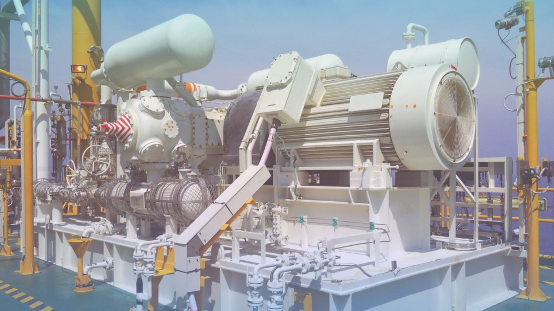
A reciprocating compressor for a vapor recovery unit of an oil and gas central processing platform
Here is a new old way of protecting your reciprocating machines from catastrophic failure and reducing the cost of repairs: the impact sensor and transmitter. Reciprocating machines are unique and do not follow the usual rules we use for condition monitoring of rotating machines. The impact sensor or transmitter uses an innovative approach and takes advantage of reciprocating machine’s failure modes, saving machines, money and reputations.
Since the dawn of the industrial age, skilled mechanics have determined the condition of machinery by listening. Tools commonly used include steel rods, screwdrivers and in some cases a stethoscope. “Let her talk to you son,” was a phrase heard by more than one apprentice being instructed by a wise old master mechanic.
Anyone who has listened carefully to operating machines recognizes a number of characteristics. There is the steady hum of a rotating machine – at a tone usually determined by shaft rotational frequency. The tone may be pure, at a single frequency, or contain overtones familiar to any musical instrument. It may be modulated, varying in intensity due to an interaction with another component or machine. Cavitating pumps generate an irregular sharp bubbling sound because that’s exactly what is happening inside the pump. All of these characteristics have well-known diagnostic interpretations in terms of rotating machinery condition.
Traditional vibration analysis focuses primarily on the steady tones generated by rotating equipment. In some cases, special accommodations have been added to identify impact type events such as the inaudible and audible clicks generated by flaws on a rolling element bearing. Although these transient clicks and impacts may be quite clear to a human ear, they typically don’t constitute a significant portion of the total energy within the overall signal sensed by a vibration transducer. Thus, while the characteristics can be heard and seen by a human with our remarkable processing ability, they won’t appear in a conventionally detected level displayed on a vibration monitor. And that’s the primary limitation of conventional vibration monitoring as a means to identify the condition of a reciprocating machine. It’s the same problem you experience attempting to converse with the person sitting next to you during a rock concert – their presumably intelligent speech constitutes a miniscule portion of the overall sound level.
Components in a reciprocating machine can be compared to many people talking in a noisy room. While the crankshaft is going round and round, rods are going back and forth reversing on every stroke. Tones may be present; however, they are typically not the primary condition characteristics. Squeaks, ticks, knocks and other assorted periodic impact type sounds are generated as components move. Clearances click, and hopefully will not bang, as forces reverse direction. There will be whooshing noises from valves opening and closing as well as flow noise through open valves. Examples of anomalies that are manifested as impact or spike type transients are knocks from loose parts and liquids in gas, clicks as clearances come together and open (often observed visually as bubbles or oil weeps) and hissing flow noise through closed valves and squealing gasket leaks. All are embedded in the busy transient sounds of a reciprocating machine in action.
From this simplified description, one can see that in terms of vibration and sound, a reciprocating machine is a quite different animal and far more complex compared to a rotating machine. For this reason, conventional vibration monitoring and analysis techniques, employed very successfully on rotating machines, don’t work very well on reciprocating machines. There is simply too much broadband noise and transient activity in a sound or vibration signal to accurately identify what a single component is attempting to say. If the vibration system is set to a high sensitivity in order to recognize small changes, you are likely to experience false trips. If the sensitivity is set too low, the monitored machine may suffer extreme damage without a trip from the vibration monitoring system.
A brilliant fellow who had “been there, heard that,” wondered whether all the transients that characterized the sound and vibration generated by a reciprocating machine could be used effectively in a new form of detection. Instead of looking at steady state tones, why not build a monitoring strategy that was very sensitive to the impacts generated by reversals unique to reciprocating machines? Let the machine work for you instead of against you. With loosening bolting and clearances, leaking valves and many more common problems in a reciprocating machine identified by impact type events, why not use this information? When ignored, conditions identified by impacts only get worse.
As the thought process evolved, it seemed logical that a reciprocating machine in normal condition should have some level and pattern of impacts. Any deviation, such as bolts or fits loosening and internal leakage, should produce a measurable change in the pattern (amplitude and number of impacts in a given time period). The theory was tested, and like so many things that are simply a new way of doing something that an old-line master mechanic relied on, it worked very well in practice.

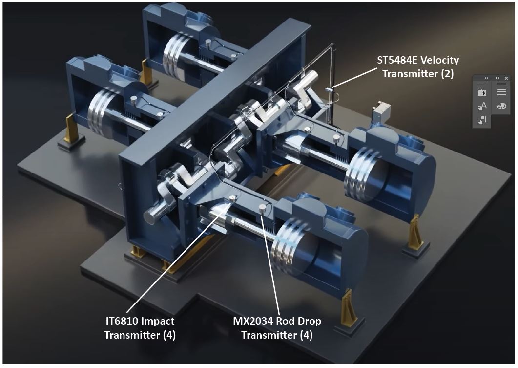
Figure 1: Metrix Reciprocating Compressor Monitoring Transmitter Suite
A gas plant in southern California has five 5,500 HP V-16 engine-driven compressors. All were equipped with conventional vibration monitors. About a year ago, one unit suffered a catastrophic rod failure in which the vibration monitoring system did not shut down the engine – even though the fractured rod had broken through the crankcase! This disaster was the final straw for a vibration monitoring system that had produced phantom alarms and trips in the past and had now failed to operate when a real failure occurred.
Recognizing that the situation with an unreliable vibration monitor couldn’t continue, the company initiated a search to find something better that would be capable of preventing another expensive failure. As a result of the search, they installed Impact transmitters and embarked on an extensive test program. The test program had two objectives: identify optimum transducer configuration and compare performance to the vibration monitoring system.
With the Impact transmitters in place and connected to analog input channels on their PLC, the system was tested with an impact wrench on crankcase through bolts. The Impact system responded immediately. Plug wires were removed to induce misfiring. The engine was overloaded to about 115%; the Impact transmitters didn’t respond to either condition. With deliberately increased valve lash, the Impact transmitter tripped – on intake valves only.
Following the test, it was concluded that the Impact system offered significantly improved protection compared to conventional vibration monitoring. The phantom alarms and trips have ended, and in one case they found a bent pushrod following warning from an Impact transmitter.
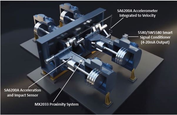
Metrix has expanded the impact transmitter functionality into the 5580 Smart Signal Conditioner and SW5580 Smart Switch. These devices take advantage of the small clicks and eventual impacts found in reciprocating machines. The same technology that was used in our innovative Impact transmitter, we used in these devices. Using the impact functionality of the 5580/SW5580 software, one can set the threshold level and the timing event to catch impact events using an SA6200A accelerometer.
In another application, a gas plant was particularly concerned about broken valve keepers. In the past, keepers have broken allowing the valve to contact the piston with serious damage occurring in less than 5 seconds. The use of accelerometer sensors with the 5580 Signal Conditioner or the SW5580 monitor, or the Metrix IT6810 Impact Transmitter, significantly increases protection against this type of keeper failure. These systems help reduce the concern about link rod failures, when wear increases bolt stress until they break. These Impact systems will recognize this type of wear, and the increasing bolt stress, prior to failure.
Another major gas plant in southern California experienced a similar epiphany. After a diet of valve and power piston parts killed the turbocharger on a large integral gas compressor, the conclusion was clear. There had to be a better way to protect these expensive machines than conventional vibration monitors. Following an extensive test program, Impact transmitters were installed as primary protection on approximately 15 gas compressors ranging up to 6,000 horsepower.
As is so often the case, the mere act of installing better protection appears to have frightened away the valve and piston failure the Impact system was designed to avoid. However, one major save, and a number of minor saves have demonstrated the effectiveness of the Impact method of protection. The major save occurred when an impact-initiated warning led to the discovery of a cracked crankshaft. As anyone who has seen one knows, the results of a crankshaft failure are not pretty, inexpensive or easily repaired! In addition to this major save, this plant has experienced a number of instances where Impact transmitters have warned of loose bolting, including a rod nut, in plenty of time to take corrective action before any damage occurred.

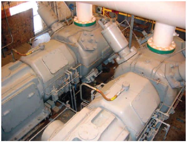
Figure 2: IT6810 Impact Transmitters Mounted on the Crosshead
A plant in Texas has close to 100 Impact transmitters installed on electric drive CO2 compressors. This facility is comprised of 30 reciprocating compressors totaling 154,000 HP and ranging in size from 8,000 HP down to 2,250 HP. In all cases, the Impact transmitters are installed on top of the crosshead guide. Some of these machines are over 50 years old and the impact transmitters have prevented potential major failures. On some relatively new machines, gaskets and bolting have relaxed during initial operation. The Impact transmitters have caught this condition in plenty of time to fix it before any damage occurred. In one case, an Impact transmitter indicated a problem that defied identification. Clearances were checked, and there weren’t any external signs of looseness such as bubbles or oil weeping. Everyone jumped to the usual conclusion – it must be the instrumentation. Another Impact transmitter produced exactly the same results. Finally, after much searching, two 1 1/8 studs were found improperly torqued. When the studs were torqued to their proper value, the Impact transmitter returned to normal – a great indication of the sensitivity of Impact monitoring technology.
By taking advantage of the two-channel 5580 and or SW5580, one can use an accelerometer mounted on the crosshead to measure acceleration on Channel 1 and impact on Channel 2. This dual functionality provides a level of comfort that the accelerometer is working when there are no impact events present.
So how does an Impact transducer perform its magic? As previously stated, the Impact transmitter, as well as an accelerometer connected to a 5580/SW5580 configured for impact, is designed for sensitivity to high amplitude, short duration transient spikes that characterize most potential problems found on reciprocating machinery. These spikes typically don’t represent a significant portion of the total energy within a steady state vibration signal. They are lost in the traditional signal processing used for monitoring rotating machines. Within the Impact transmitter, or accelerometer connected to a 5580/SW5580 configured for impact, special peak detection circuitry captures and counts impact events above a threshold value during a specified length of time. This counting method has proven very reliable in practice. Transient conditions where impact events appear and go are differentiated from mechanical flaws where impact events appear and stay.

Figure 3: Metrix Reciprocating Compressor Monitoring Sensor Suite
(Voltage Input: Dynamic Signal and 4-20mA Output)
Since the Impact transmitter, or the accelerometer, is focused on identifying conditions, such as looseness, cracks and leakage, it is typically mounted on the crosshead or distance piece perpendicular to rod motion. The transducers produce a 4-20 mA output equivalent to the number of impact events above an adjustable threshold level within a preset time window. In this configuration, the IT6810 transmitter, or the 5580/SW5580 configured for impact, is a very cost-effective addition to the control and monitoring systems present on most reciprocating machines.
If you are responsible for reciprocating machinery and you are looking for a new but thoroughly tested means for protection, our impact suite of products is a good choice. They effectively utilize the inherent dynamic characteristics of a reciprocating machine to warn and trip in the event of defects such as loose bolts, cracked parts, valve breakage, rider band or ring problems unique to this type of machinery. Our Impact monitoring products work with reciprocating characteristics rather than against them to provide you with confidence that your machinery will not fail unattended and unnoticed.
Download our Stop Damage to Reciprocating Machines Application Note

